3, 4, 5, 6, & 8 Wire Throttle Position Sensor Wiring Diagram TPS
Sign In Forgot Password? Reset We will send a password reset link to your email address. Are you an Agent? Login here You will be taken to the agent interface. Haltech Support Center | Sign In
Throttle Body Position Sensor Wiring Diagram Needed
The throttle position sensor (TPS) is an essential component of a vehicle's engine control system. It provides crucial information about the position of the throttle valve, allowing the engine control unit (ECU) to adjust the air-fuel mixture and optimize engine performance.

Ford Throttle Position Sensor Wiring Diagram Artsian
Educational video on how the Throttle Position Sensor (TPS) works and how to test for proper operation using a digital volt meter and a Digital Storage Oscil.

Ford Throttle Position Sensor Wiring Diagram
A throttle Position Sensor or TPS is installed in the throttle body and is always in contact with the throttle valve or gas valve. This TPS sensor functions to detect changes in the position of the gas throttle and then converts it into an electrical signal which will be sent to the ECU as an input signal.
6 Pin Throttle Position Sensor Wiring Diagram Wiring Harness Diagram
THROTTLE POSITION SENSOR explanation for wiring diagram, troubleshooting and simplify tutorial Automotive electronics from schematics by Joseph 10.9K subscribers Subscribe Subscribed 141.

Fungsi Throtle Position Sensor ( TPS ) Dan Cara Kerjanya Pada Mesin
A throttle position sensor ( TPS) is a sensor used to monitor the air intake of an engine. The sensor is usually located on the butterfly spindle/shaft, so that it can directly monitor the position of the throttle. More advanced forms of the sensor are also used.

Repair Guides Electronic Engine Controls Throttle Position Sensor
A throttle position sensor (TPS) is an electronic device that monitors the position of the throttle valve, which controls the amount of air entering the engine. The TPS sends signals to the engine control module (ECM), which uses the information to adjust the fuel injection and ignition timing for optimal engine performance.
Mustang throttle position sensor
Throttle Position Sensor (TPS) diagram provides a comprehensive visual representation of a critical component in modern engine control systems. This visual guide illuminates the TPS's role in monitoring and relaying the throttle position to the engine control unit, influencing crucial aspects of engine performance.

P0122 Code Throttle Position Sensor/Switch A Circuit Low Input In
Step 1: Locate the sensor. The throttle position sensor is mounted to the throttle body on top of the engine. Step 2: Disconnect the negative battery cable. Disconnect the negative battery cable and set it aside. Step 3: Remove the sensor electrical connector. Remove the electrical connector by pushing down on the tab and sliding it off.

Toyota Throttle Position Sensor Wiring Diagram Naturalfer
The linkage to a throttle position sensor should use most of the rotating range of the throttle position sensor. This can be adjusted by changing the ratio of the linkage. Also, please make sure that a small amount of the sensor's travel is being used at idle. You will want a TPS voltage at idle of at least 0.35 volts. This is done to allow the.
2014 Tundra SR5 Throttle position sensor wiring diagram Toyota Tundra
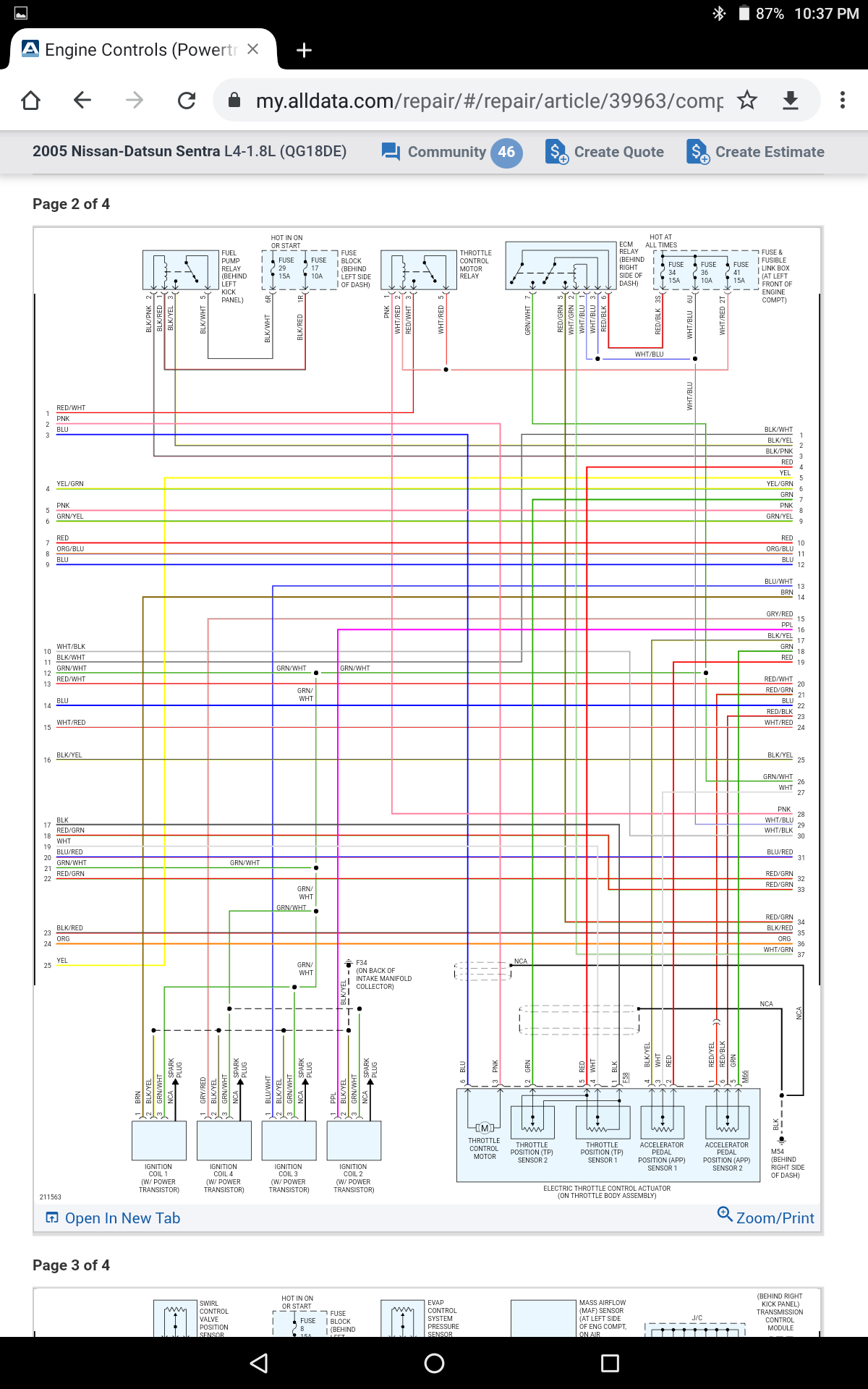
The 6 pin throttle position sensor (TPS) wiring diagram is a crucial component in the automotive industry.It is responsible for providing the engine control unit (ECU) with information about the position of the throttle valve. This information helps the ECU to determine the appropriate fuel injection and ignition timing.The wiring diagram consists of six pins that connect the TPS to the ECU.

THROTTLE POSITION SENSOR, P/N 5006484 INSTALLATION INSTRUCTIONS
The Ford Throttle Position Sensor Wiring Diagram is an essential resource for every automotive enthusiast and technician. This diagram provides a detailed visual representation of the electronic circuitry within the throttle position sensor (TPS), helping to better understand its intricate function and significance in a Ford vehicle's.

hfjggjjmhmh [6+] 6 Pin Throttle Position Sensor Wiring Diagram, Gm
The throttle position sensor diagram also helps understand the various connections between these components. The potentiometer is typically connected to the throttle shaft via a linkage, allowing it to accurately measure the throttle valve's position. The potentiometer's electrical signals are then transmitted to the ECU through wiring.
Ford Tps Sensor Wiring Wiring Library Throttle Position Sensor
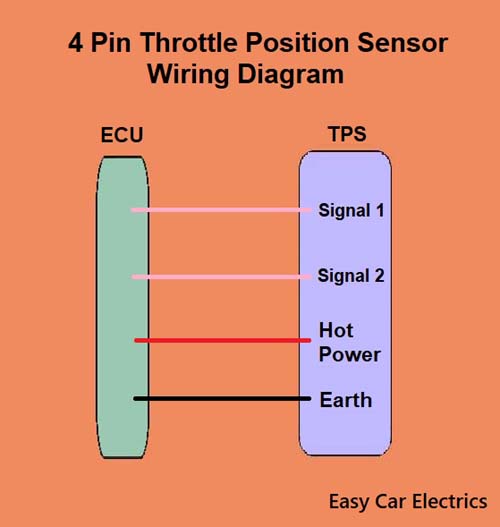
By Lambda Geeks The 4 wire throttle position sensor is an essential component in modern automotive engines. It measures the position of the throttle valve and provides this information to the engine control unit (ECU). This sensor helps the ECU determine the appropriate fuel-air mixture and ignition timing for optimal engine performance.

Repair Guides Components & Systems Throttle Position Sensor
The throttle position sensor (TPS) is a device on the engine that detects the position of the throttle plate. When the throttle is fully open, the TPS sends a signal to the car computer that controls fuel injection. It also sends a signal to the ECU when the throttle is closed, so it can adjust timing and fuel delivery accordingly.

hfjggjjmhmh [6+] 6 Pin Throttle Position Sensor Wiring Diagram, Gm
The throttle position sensor ( TPS) wiring diagram is an essential component of a vehicle's engine management system. It provides valuable information about the position of the throttle valve, allowing the engine control unit (ECU) to adjust the fuel injection and ignition timing accordingly.